Electromechanical servo presses
OPERATING SYSTEMS
We can offer you three different solutions for programming the joining functions and/or inputting the parameters:
 EMG SYSTEM SOFTWARE FOR “PROGRAM INPUT”
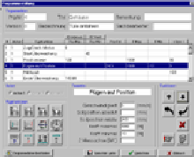
The simple programming of the joining functions can be realised via a PC or a laptop. The PC connection is only required when creating new programs or changing the parameters. The creation of the program sequence and the input of the parameters for the joining functions take place in a very simple and almost self-explanatory mask.
If you require a graphic evaluation of the joining process using envelope and window technology or documentation of the press-fit curves and measured values, the PC must be online to the system.
PROGRAMMING VIA SIEMENS OPERATING DEVICE TP 277 IN CONJUNCTION
WITH A SIEMENS S7
If the machine is controlled with a Siemens S7 PLC, it is possible to create joining programs, machine parameters, create monitoring windows and visualise the joining process via a TP 277. For this purpose, we provide an example program and data blocks for the S7, as well as the projected interfaces for the TP 277, which can be implemented in an own project.
 EMG OPERATING PANEL
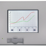
Programming, operation and visualisation in a compact form. The simple programming of the joining functions, the operation of the machine (if required) and the visualisation is carried out by our operating panel (5.7″).
The force-displacement curve, the result of the joining process (OK/NOK) and several statistical data are displayed. However, the operating panel does not allow documentation. Only the data of the last curve is saved.
Optionally, the machine control (operating mode pre-selection, controller in manual mode, start button, etc) can be realised via the operating panel. Sample interfaces and programs for individual workstations are available for this purpose and can also be customised.
In addition, we will offer the setting of windows for evaluation in the future.
The device has three slots for expansion cards (e.g. I/O cards) with which machine control or communication with a higher-level controller can be realised.
One of the slots can alternatively be used for an “Anybus®” embedded bus module (e.g. Profibus DP).
A particularly economical solution is the internal controller in the control section of the converter combined with our operating panel.
Features and advantages
- Visualisation without PC
- Connection via Ethernet to the internal controller
- Display of curves, results (OK/NOK) and statistical data
- Display size 5.7″, touch screen
- Panel or housing mounting
- Modular concept – cost saving
Technical data
- Colour TFT display, input via touchpad
- 5.7″ display size
- 320×240 pixel resolution
- CPU 266 MHz, 32 MB application data memory
- Dimensions (WxHxD [mm]) 194x172x52 (+front panel 6 mm)
- Installation dimensions (WxH [mm]) 184×162
(in the corners Ø 5mm holes – ask for an installation sketch) - Weight 1.5 kg
- Operating conditions 0°C to 50°C
- Protection class IP20 (front IP65)
- 24VDC supply voltage, 1A current consumption
- Interfaces:
1 x Ethernet 10/100 Base T (RJ45)
2x USB (1x front,1x rear)
2x CAN bus interfaces
2x RS232
1x RS485
3x expansion slots
Options
- I/O card (only available when installed)
12 digital inputs
8 digital outputs
4 digital inputs/outputs
2 digital inputs can also be used as counters
2 analogue inputs 0-10V or 0-20mA
1x CAN interface - Profibus-DP master bus module (only available when installed)
for connecting max. 125 slave nodes
Connection through 9-pin Sub-D
4 diagnosis LEDs - Profibus-DP slave bus module (only available when installed)
1x Profibus slave interface DP
Connection through 9-pin Sub-D
4 diagnosis LEDs
Technology
Electromechanical servo presses
Downloads
Your contact person
Dipl.-Ing. (FH)
CHRISTIAN HILSMANN
will be happy to answer your questions – by e-mail or on the phone

c.hilsmann@emg-engineering.de
+49 (0) 29 51 / 93 883 – 13
